

Convolution, the mathematical, local operation defined in Section 3.1 is central to modern image processing. The basic idea is that a window of some finite size and shape--the support--is scanned across the image. The output pixel value is the weighted sum of the input pixels within the window where the weights are the values of the filter assigned to every pixel of the window itself. The window with its weights is called the convolution kernel. This leads directly to the following variation on eq. . If the filter h[j,k] is zero outside the (rectangular) window {j=0,1,...,J-1; k=0,1,...,K-1}, then, using eq. , the convolution can be written as the following finite sum:

This equation can be viewed as more than just a pragmatic mechanism for smoothing or sharpening an image. Further, while eq. illustrates the local character of this operation, eqs. and suggest that the operation can be implemented through the use of the Fourier domain which requires a global operation, the Fourier transform. Both of these aspects will be discussed below.


where w1 and w2 are arbitrary complex constants and xo and yo are coordinates corresponding to arbitrary spatial translations.
Two remarks are appropriate at this point. First, linearity implies (by choosing w1 = w2 = 0) that "zero in" gives "zero out". The offset described in eq. means that such camera signals are not the output of a linear system and thus (strictly speaking) the convolution result is not applicable. Fortunately, it is straightforward to correct for this non-linear effect. (See Section 10.1.)
Second, optical lenses with a magnification, M, other than 1x are not shift invariant; a translation of 1 unit in the input image a(x,y) produces a translation of M units in the output image c(x,y). Due to the Fourier property described in eq. this case can still be handled by linear system theory.
If an impulse point of light d(x,y) is imaged through an LSI system then the impulse response of that system is called the point spread function (PSF). The output image then becomes the convolution of the input image with the PSF. The Fourier transform of the PSF is called the optical transfer function (OTF). For optical systems that are circularly-symmetric, aberration-free, and diffraction-limited the PSF is given by the Airy disk shown in Table 4-T.5. The OTF of the Airy disk is also presented in Table 4-T.5.
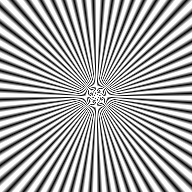
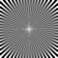
If the convolution window is not the diffraction-limited PSF of the lens but rather the effect of defocusing a lens then an appropriate model for h(x,y) is a pill box of radius a as described in Table 4-T.3. The effect on a test pattern is illustrated in Figure 23.

 a) Test pattern b) Defocused image
 Figure 23: Convolution of test pattern with a pill box of radius a=4.5 pixels.
The effect of the defocusing is more than just simple blurring or smoothing. The almost periodic negative lobes in the transfer function in Table 4-T.3 produce a 180deg. phase shift in which black turns to white and vice-versa. The phase shift is clearly visible in Figure 23b.

Figure 24: Coordinate system for describing h[j,k]
When we examine the convolution sum (eq. ) closely, several issues become evident.
* Evaluation of formula for m=n=0 while rewriting the limits of the convolution sum based on the "centering" of h[j,k] shows that values of a[j,k] can be required that are outside the image boundaries:

The question arises - what values should we assign to the image a[m,n] for m<0, m>=M, n<0, and n>=N? There is no "answer" to this question. There are only alternatives among which we are free to choose assuming we understand the possible consequences of our choice. The standard alternatives are a) extend the images with a constant (possibly zero) brightness value, b) extend the image periodically, c) extend the image by mirroring it at its boundaries, or d) extend the values at the boundaries indefinitely. These alternatives are illustrated in Figure 25.

Figure 25: Examples of various alternatives to extend an image outside its formal boundaries. See text for explanation.
* When the convolution sum is written in the standard form (eq. ) for an image a[m,n] of size M x N:

we see that the convolution kernel h[j,k] is mirrored
around j=k=0 to produce
h[-j,-k] before
it is translated by [m,n] as indicated in eq. . While some
convolution kernels in common use are symmetric in this respect,
h[j,k]= h[-j,-k], many are not. (See
Section 9.5.) Care must therefore be taken in the implementation of filters
with respect to the mirroring requirements.
* The computational complexity for a K x K convolution kernel implemented in the spatial domain on an image of N x N is O(K2) where the complexity is measured per pixel on the basis of the number of multiplies-and-adds (MADDs).
* The value computed by a convolution that begins with integer brightnesses for a[m,n] may produce a rational number or a floating point number in the result c[m,n]. Working exclusively with integer brightness values will, therefore, cause roundoff errors.
* Inspection of eq. reveals another possibility for efficient implementation of convolution. If the convolution kernel h[j,k] is separable, that is, if the kernel can be written as:

then the filtering can be performed as follows:

This means that instead of applying one, two-dimensional filter it is possible to apply two, one-dimensional filters, the first one in the k direction and the second one in the j direction. For an N x N image this, in general, reduces the computational complexity per pixel from O(J* K) to O(J+K).
An alternative way of writing separability is to note that the convolution kernel (Figure 24) is a matrix h and, if separable, h can be written as:

where "t" denotes the matrix transpose operation. In other words, h can be expressed as the outer product of a column vector [hcol] and a row vector [hrow].
* For certain filters it is possible to find an incremental implementation for a convolution. As the convolution window moves over the image (see eq. ), the leftmost column of image data under the window is shifted out as a new column of image data is shifted in from the right. Efficient algorithms can take advantage of this and, when combined with separable filters as described above, this can lead to algorithms where the computational complexity per pixel is O(constant).
i) Compute A( ,
, ) =
F{a[m,n]}
ii) Multiply A( ,
, ) by the
precomputed (
 ,
, ) =
F{h[m,n]}
iii) Compute the result c[m,n] =
F-1{A( ,
, )*(
)*( ,
, )}
)}
* While it might seem that the "recipe" given above in eq. circumvents the problems associated with direct convolution in the spatial domain--specifically, determining values for the image outside the boundaries of the image--the Fourier domain approach, in fact, simply "assumes" that the image is repeated periodically outside its boundaries as illustrated in Figure 25b. This phenomenon is referred to as circular convolution.
If circular convolution is not acceptable then the other possibilities
illustrated in Figure 25 can be realized by embedding the image
a[m,n] and the filter ( ,
, ) in
larger matrices with the desired image extension mechanism for
a[m,n] being explicitly implemented.
* The computational complexity per pixel of the Fourier approach for an image of N x N and for a convolution kernel of K x K is O(logN) complex MADDs independent of K. ere we assume that N > K and that N is a highly composite number such as a power of two. (See also 2.1.) This latter assumption permits use of the computationally-efficient Fast Fourier Transform (FFT) algorithm. Surprisingly then, the indirect route described by eq. can be faster than the direct route given in eq. . This requires, in general, that K2 >> logN. The range of K and N for which this holds depends on the specifics of the implementation. For the machine on which this manuscript is being written and the specific image processing package that is being used, for an image of N = 256 the Fourier approach is faster than the convolution approach when K >= 15. (It should be noted that in this comparison the direct convolution involves only integer arithmetic while the Fourier domain approach requires complex floating point arithmetic.)
