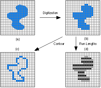


When dealing with a region or object, several compact representations are available that can facilitate manipulation of and measurements on the object. In each case we assume that we begin with an image representation of the object as shown in Figure 8a,b. Several techniques exist to represent the region or object by describing its contour.
The codes associated with eight possible directions are the chain codes and, with x as the current contour pixel position, the codes are generally defined as:


Figure 8: Region (shaded) as it is transformed from (a) continuous to (b) discrete form and then considered as a (c) contour or (d) run lengths illustrated in alternating colors.
* Each code can be considered as the angular direction, in multiples of 45deg., that we must move to go from one contour pixel to the next.
* The absolute coordinates [m,n] of the first contour pixel (e.g. top, leftmost) together with the chain code of the contour represent a complete description of the discrete region contour.
* When there is a change between two consecutive chain codes, then the contour has changed direction. This point is defined as a corner.
The "crack" code can be viewed as a chain code with four possible directions instead of eight.

 (a) (b)
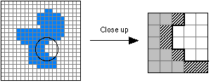
Figure 9: (a) Object including part to be studied. (b) Contour pixels as used in the chain code are diagonally shaded. The "crack" is shown with the thick black line.
The chain code for the enlarged section of Figure 9b, from top to bottom, is {5,6,7,7,0}. The crack code is {3,2,3,3,0,3,0,0}.
